Don't blink an eye! Learn the basics of the program editor
This is the introductory project to learn how to use the program editor and programming concepts. Students will build a simple circuit and write code to make an LED light blink on and off.
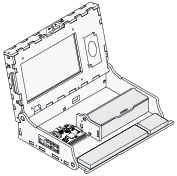 Piper Computer Kit
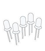 LED (Green)
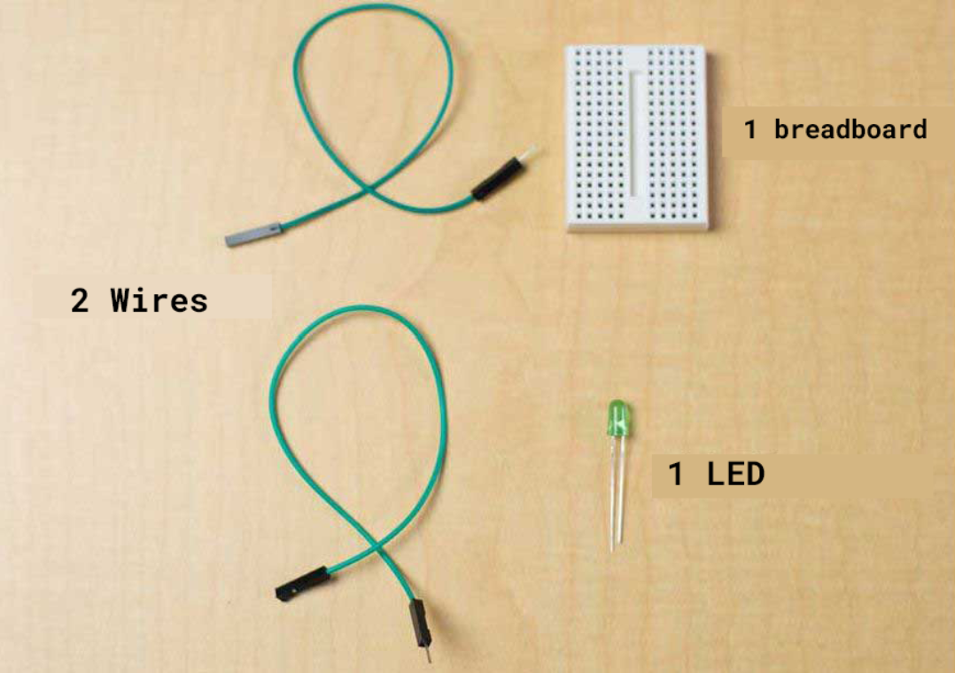
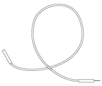 2 Wires (any color)
 Breadboard
Students need to understand that each GPIO pin on the Raspberry Pi is assigned a specific number. They’ll learn to create PiperCode programs to control these GPIO pins connected to their breadboard, which will, in turn, control the LED light output. They’ll write a loop that runs continuously, with code blocks inside to turn the LED on, pause, and then turn it off, causing the LED to blink.
Take out the inventory you see in the image below.
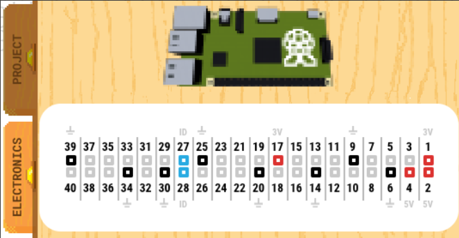
The Raspberry Pi has GPIO pins. Look at the image to see how they are numbered.
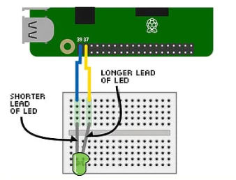
Connect your LED and jumper wires to the breadboard and Raspberry Pi as shown in the image below. Pay close attention when connecting the legs of the LED to ensure it is in the correct orientation.
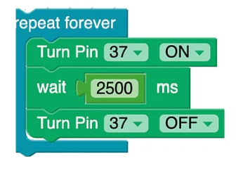
Drag out a Pin On/Off block to turn pin 37 ON. Then start your code.
Drag out a second Pin On/Off block to turn pin 37 OFF. The start your code.
Put the two Pin On/Off blocks in a Repeat Forever block. Now start your code again.
Add a Wait block to make the lights blink more slowly.
Change the wait time and customize the blinking!